Tuesday, September 19, 2017

Mask Impact on Dimensional Accuracy

A number of things are going on in parallel on this project.  I have the PCB coming from China, a case in draft on the printer now, the software now being rewritten as a new version with some learnings from V1, some testing of various sensors, and some comparisons of the mask in operation.

Here are the results of one of those tests.  There is clearly an improvement in dimensional accuracy between the No Mask and the Mask versions of these objects from the center, edges, and corners of the build plate.  I would caveat this with two observations.  First that my 16quid caliper, combined with my coordination, is incapable of getting consistent readings at this resolution.  Second that I am hoping to further improve the accuracy of the base data read by my UV meter to improve these results.

The Test Results

The Calibration Objects!


Friday, September 15, 2017

The NanoDLP Mask Wizard and the Wanhao D7

The layout and orientation of the build plate as displayed by NanoDlp versus what is actually displayed by my printers confuses me every time I look at it.  It may not be confusing for most people ... but I confess that it is to me!  This has been particularly true when it comes to the NanoDlp Mask Generation Wizard.

By default NanoDlp presents a 10 by 5 cell matrix for entry of a mask.

When translated to the Wanhao D7 this is what we see.
When the entries are reversed for a 5 by 10 cell matrix...

...we get the result we need.  It is also important to note that entry of data to NanoDlp, if doing so in the normal mode of top left to bottom right, means doing your UV readings from the bottom right corner and then up on the D7.

Sunday, September 10, 2017

UV Meter - Prototype

Have been making some progress on a prototype for my DUP 3D Printer Calibration UV Meter.  Maybe just DUPUVM for short?

A breadboard prototype has been assembled and code written to drive it.
The case design has been evolved a little to match the PCB.
An initial PCB has been ordered from Seeed Studios in China.  

Further progress on the case will wait for the PCB.  Software has a ways to go yet but is far enough along that I felt comfortable ordering the PCB.  The first batch of PCBs will still be prototypes which explains some of the extra contact point you can see above.

The meter will function as follows:

  1. Readings can be recorded from the built in LCD display or they can be captured either via a Bluetooth terminal session or by connecting the device to the Arduino development environment and using the terminal there.
  2. Two LCDs display the status of data capture with solid green indicating a good solid reading, flashing green and red indicating a fluctuating reading, and solid red indicating that the reading is not stable enough to record.
  3. When a stable reading can be taken a single press of the button will display the current light intensity on the LCD, broadcast it out the serial port, and the two LEDs will both illuminate.
  4. A second press of the button will send a delimiter and will start the next reading cycle.   Note that holding the button down at this point, for more than a second, will send a line delimiter.
  5. If you are taking the data capture route the above process will result in you having a comma separated file for import into the spreadsheet that calculates parameters for generating the mask in NanoDlp.


xx

Thursday, September 7, 2017

UV Meter - Concept

In my previous article I discussed building a mask for NanoDLP using a UV meter that was somewhat cobbled together from stuff that I had laying around.  Here I present a slightly more grown up version of said meter!


This would be a fairly small package enclosing an Arduino Nano, connected to a USB power source, a 128x64 LCD display, two push buttons, one LED, a photo resistor, a 10k resistor, and a bluetooth adapter.

The LED (green) will flash when a stable reading is being obtained.

Pressing either button when a stable reading is present will cause a reading to be taken and displayed on the LCD.

The above reading will also be output to the serial port and and broadcast by the bluetooth adapter.  The value output will be terminated with a comma.

Pressing both buttons will output a newline to the serial port to be broadcast by the bluetooth adapter.  In this manner a CSV (comma separated values) buffer can be built for capture on the PC connected to the meter.

The photoresistor mounted on the bottom of the meter will fit into the grid designed and printed for the purpose of measuring UV output of the 3D Printer.

In operation the meter could be used either disconnected, and taking a single reading at a time transcribed from the LCD display, or connected to a computer where the entire stream of readings is buffered and captured.

Wednesday, September 6, 2017

Generation of a NanoDLP Mask for the Wanhao D7

Update as of 17/9/2017:  This is a very flawed article as I confess in a later post here.  Flawed, yet because the D7 UV light is distributed so heavily to the center, it still worked well!  Sorry for any confusion and that I did not post this confession sooner (though I did make a note on the 14th)!

I finally decided to invest the effort in creating masks so that my build plate is evenly exposed to radiation from the UV LED Array of the Wanhao D7 3D Printer.    The annotation on the following images explains the process.  Links are at the bottom.

Note that as of 14:53 on 7/9/2017 I am chasing a little bit of under cure on the edges even with the measurements.  Things are much, much better than without the mask, just not perfect!

Note that as of as of 16:24 on 14/9/2017 I need to 'fess up that my understanding of how mask generation works in NanoDLP was pretty flawed below.  Stay tuned.

Created a printable grid that matches the default grid on the NanoDLP mask generator (e.g. 10 columns by 5 rows).  The tabs can be used to secure the grid.  Theoretically the one without tabs could be printed on the D7.  The camera adapter was my first plan but the iPhone light meter app I tried could not detect the UV well enough.  The little square thing is a mount for the photoresistor that I ended up using.
Ultra simple Arduino circuit.  Photoresistor to ground and to A5 with a 10k resistor to +5v.  Read A5 averaging 2 seconds of inputs 100ms delayed from each other (20 in other words) and display the result.
Printed matrix secured to the printer with the photoresistor in a cell.


Top right is the output from the Arduino.  Bottom right is the monitor built into the printer.  Left is the spreadsheet that I used to calculate the mask values.
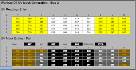
View of the completed spreadsheet.  Layer cure time will need to be increased by the stated percentage.

The above spreadsheet also has tables for subsets of the build platform.  This one only uses two fifths of the build plate and as such only increases cure time by 11%.  The white area of the first table is the printable area to model.  On the second table the yellowish cells represent unprintable but the light grey ones are adjustable to be useable.


Mask as generated.  Located in ~/printer/public/plates on the NanoDLP instance.


Proof is in the pudding.

Grid on Thingiverse
Arduino Sketch
NanoDlp Mask Calculator
Link to Mask - Use at your own risk!

Parts needed for your own measuring device:
  1. Photoresistor -  Search for "5516 Photoresistor Sensor Detection Light Dependent Resistor". Interestingly I did not buy this for UV sensitivity but it works fine and I wonder if other photoresistors might as well.  If you are reading a difference of more than 30-40% from the middle to the edges of your display it might be the photoresistor.
  2. 10K Resistor - Used for the other leg of a classic voltage divider.  
  3. Arduino Uno - Search for them on eBay.  You can get clones from China for a couple of quid if you are patient with shipping times.
Comparison of masks for my two printers.
Interestingly the printer on the left has a glass plate behind the LCD and the one on the right does not.

Here is the test piece from my second printer.  Same issue with measuring the little pointy things...there is a slight under cure at the edges.

Calibration pieces from printer #1.  First time anything has stuck to that corner!

Closeup of the above calibration pieces.  Can you tell which one was center, versus side, versus corner?


Monday, September 4, 2017

Resin Mixing Pump


I have noticed that FTD Snow White, a heavily pigmented resin, tend to separate over a long print.  Someone on the D7 Facebook Group had used a dosing pump to keep resin mixed so I decided to do the same.

Here is the pump that I used (from Amazon UK).  The tubing that I used was from eBay and was described black silicon tubing with an inner size of 2mm and an outer of 4mm.

The pump vibrates when it operates so it should probably be turned off when the printer is curing a layer.  This means putting it on the 2nd fan output on the power supply so you can control it with "M106 P1 S255" for on and "M106 P1 S0" for off.  I guess the alternative would be to have it off the printer and running constantly?

The mount that I designed for the pump is pretty simple and is available on Thingiverse for download.  Ideally I would have liked the hoses to feed around the back of the vat but there just was not enough clearance for the build plate to travel.  As you look at the picture of the printer the left is suction and the right is output.  I route the suction tube to the near right corner and the output to the far left corner.   The tip of the input tube is cut at an angle so it does not attach itself to the FEP.


Controlling the pump entails putting the following gCode into the printer setup:

Below is a ten hour print.  There is no sign of pigment leaching which I would have  expected towards the end of the ten hours.