Evolution of a Blog

This blog has evolved as I have as a maker. It starts at the beginning of my journey where I began to re-tread my tires in the useful lore of micro electronics and the open-source software that can drive them. While building solutions around micro-electronics are still an occasional topic my more recent focus has been on the 3D Printing side of making.

Saturday, October 14, 2017

NanoDlp and the topic of Masks - Part 5 - Another Meter

One last meter!  This is probably the one that I should have done in the first place but it only took today to do it while I am still perfecting the bigger one!  Lot more fun that one but this one is probably a lot more practical.

It consists of a 3D Printed case, an Arduino Nano, a Photoresistor, a 10K resistor, and a couple of wires.  Uses a mini-USB cable for communication back to either a terminal program or the Arduino IDE running on a PC or laptop.  Power is provided by the USB cable.

Its output is a continuous stream of readings that represent an average light level across the past second.  Each reading includes a quality (based on stability of the reading) metric where 0-1.5 is good, 1.5-3.0 is less good, 3.0 to 6.0 is bad, 6.0 to 10.0 is real bad, and over 10.0 is just plain crap.

Meter is designed to be used with a printed grid which ensures good positioning.

Positioning is very important and sensor needs to be flush to the screen.

Sample output shows the readings with their quality.
Here is the code for the Arduino
Here are the files for the Case

Note that there are two versions of the case, the one shown above, and the one shown below.  The one above uses a 3D printed grid for alignment and the one below is designed to be positioned on the screen directly aiming for the calibration squares displayed by NanoDlp.

Assembly Instructions


Parts Needed: 3D printed case with rest button, some shrink wrap tubing, photoresistor (GL5528) and normal 10k resistor, three female patch cables, and an Arduino Nano. 
This is how they need to be connected.  Black will plug into the ground pin, Orange to 5v, and Yellow to analog pin 5. 


Finished and connected to the Arduino Nano. 

Bottom view with everything  in the case.

Top view.  The button allows you to reset the Nano.  This can serve as a marker if you are using the meter to measure a matrix of cells. The USB connector is not shown but is on the left end of the case.  The pins shown are for ICSP programming of the Nano (so you probably don't need to care)!
Left end of the case showing access to the USB connector.

NanoDlp and the topic of Masks - Part 4 - More Stuff

I have a couple copies of my meters out for some testing so thought that I would do an update in regards to my own progress now that I am testing in more earnest.

Summing it all up:  I am a little frustrated!  The meter works fine using it in the manner that NanoDlp expects...namely measuring light intensity within cells as you adjust that cell on NanoDlp.  What is not working is when I take 50 readings (which I can do in minutes) and feed them to my spreadsheet to have the input prepared for NanoDlp.  I was hoping to get to a 1 or 2% deviation on a verification measurement of the brightness once my mask is applied but I don't.

First a brief overview of operation of the meter.

  1. Connect it to power using a mini USB cable attached to either a power supply or a PC.
  2. If you are using a PC, and the Arduino IDE or a terminal program, to read from the meter then skip the next step.
  3. Connect a terminal to the meter using bluetooth.  It should advertise itself as an HC-06 and the password will be "1234".   Start a capture (depending on what you are using).
  4. To put the meter in a mode where it just measures continuously you need to reset it using a paperclip through the hole on the top of the case.   When the meter resets you will have an option to select its mode of running and what sensor it will use.
  5. Assuming we are going to measure, place the probe with the appropriate sensor on the first cell of the display (bottom right) and press the button.  It is very important that the photoresistor be flush with the build surface!
  6. The meter will wait for a stable reading before sending it across bluetooth/usb and putting it on the screen.
  7. When the meter has confirmed the reading move it to the next cell.
  8. When you have moved to the next column press the button longer, for over a second, and a new line will be sent instead of a comma.
  9. Finish measuring all the cells.
  10. Back on your host you should see 10 rows of readings!
When I plug these into my spreadsheet it all seems like it is going to work.  I copy the data for the suggested mask and paste it into NanoDlp in hopes that I will find my readings across the mask to be flat...and they are not!

Spreadsheet is Here

There seems to be a lot of variation between reads of the light levels.  I am not sure if this is a factor of my printers or the photoresistor that I am using.  I have been focused on the older of my two printers but now I am going to spend some time with the newer.

Sunday, October 8, 2017

NanoDlp and the topic of Masks - Part 3 - Assembly and Operation

Click for Article
The voltage divider circuit this project uses is shown here.  R1 is the photoresistor.  R2 is the 10k resistor.  Vin is the battery which in my case is a 1.5v AA battery.  Vout is the volt ohm meter.  In the next picture you can see the assembled circuit.

The next picture shows the completed circuit based on an Arduino Uno.  The 10k resistor bridges Ground and Analog Pin 3.  One end of the photoresistor goes to the 5v power pin.  The other end goes into Analog Pin 3 with the 10k resistor.

The sketch for the Arduino Uno is here.  It will output (to the serial pins) an analog voltage reading every second that is an average of twenty readings for that second.  A quality metric will also be output where you would like to see a reading of 1.5 or less indicating that the input was stable.

Finally, a first attempt to use the "hopefully good enough" meter!  I have gone into the NanoDlp Mask Generation Wizard and changed the build area dimensions to 10 and 5 and the measurement point dimensions to 200.  From here it is up to you as I am still working on my spreadsheet that I hope will simplify a slightly painful process from this point.

You need to measure the output of the cells displayed on the print surface while adjusting the mask values shown by the wizard.  I would recommend that you start by ignoring the outer two rows and columns as that will shorten your task AND also shorten the additional exposure time that would be needed if you included them.

Your mission is to adjust the cells such that they all project the same amount of light with the ones on the outside starting at 255 and going down with the ones in the center being somewhat lower than that and going up as you move out from the center.

This is a painful process!  This is why I am working on a spreadsheet to help take some of the pain away.  Unfortunately it is frustrating me at the moment as the results of the mask, when I measure light output, is not as I expect it to be!


Friday, October 6, 2017

NanoDlp and the topic of Masks - Part 2 - Background

Obviously there are a lot of people getting great results without using a mask.  There are a number of factors that can help to make this possible.  Resin's, like the old days of film photography, have a latitude of exposure.  Some are narrow and some are wider.  Models also have a latitude within which they can tolerate under or over exposure.  Some people might print primarily in the center of the build plate knowing the fringes are dangerous.  But if you want to be able to rely on most of your build plate delivering as good a result as the center, or if you want dimensional accuracy for your prints regardless of where they are located in the build envelope, you need a mask!

So how do you get one and how much is it going to cost you?  What I am going to describe is not the only way to skin this cat as there is also a way to use a digital image of your printer's display.  The method that I will describe is using electronic measurement from the surface of the LCD.

The default setup for NanoDlp assumes that you have a radiometer that can be used to measure the intensity of the UV in each of the cells displayed by the mask generation wizard.  Those puppies are expensive though you can find cheap ones aimed seemingly at the sunburn crowd?  Not sure how that works for a printer!

My Super Duper Meter
My thought was to build my own radiometer customized to the NanoDlp environment.  I have been working on it for a while and keep finding ways to either fix something that I did wrong, improve it, or just over engineer it (some more)!  I think it will be a cool thing for creating a mask, particularly if you have multiple printers or just like gadgets, but it is probably overkill for someone that wants a "good enough" mask for a $500 printer! 

Comparison of Meters Output
An interesting find, however, came out of my search for a UV sensor for my meter.  I finally found one that worked, a VEML6070 UV Sensor, but noticed three things.  First, the light intensity levels being detected by the UV sensor were pretty narrow compared to those detected by a visible light spectrum photoresistor sensor (a GL5288).  Second, the pattern of light, and more importantly, the levels of light, detected by the two sensors correlated strongly.  This makes sense given that 405nm, as emitted by the Wanhao D7 UV LED array, is pretty much at the boundary of visible light.  It makes even more sense that when adding the incidental visible light that the array also produces, that there would be a good reading from the GL5288.  Third, and finally, the VEML6070 would have been the most expensive component of my solution compared to the photoresistor which would have been one of the cheapest!

Parts Needed for a "Good Enough" Meter
So here is what you need for a bare bones mask calibration meter.  One photoresistor (GL5288), one normal 10K resistor, a battery (ideally 9v), some wire, and a digital volt-ohm meter.  I am talking less than $10 here...and you may already have the meter.

Part of the "Spreadhseet"
The photo resistor changes resistance depending on the intensity of the light it sees.  There a circuit called a voltage divider that comes into play for this project.  A voltage divider is one of the most simple and useful circuits out there.   You can take two resistors of known values, connect them to a power source of a known value, and have the voltage divided with the outputs calculated using a simple formula.  For our project we will know the power going in, we will know the resistance of one of the two resistors, and we can measure the voltage that results from whatever light level is impacting the GLS5288.  This voltage can then be used as a proxy for a light level reading to generate a mask in NanoDlp (with a little help from a spreadsheet that converts the voltages into input for NanoDlp).

I struggled a little trying to decide whether to base my "Good Enough" meter on a Volt Ohm Meter or on an Arduino and decided to feature the traditional meter...because it is a traditional meter.  My thought process being that most people would know what one was and how to use it. I have now decided to mention both so below you will see the parts needed if you go the Arduino route.
Parts Needed for a "Good Enough" Arduino Based Meter 

The next article(s?) will walk through creating and using this low cost mask making meter and spreadsheet.

NanoDlp and the topic of Masks - Part 1 - Introduction

3D Printers that use a non coherent light source (e.g. DUP and DLP) will have an imperfect distribution of light at the printing interface.  Printers like the Wanhao D7, with a single UV LED light source will be particularly bad with a significant difference in light intensity between the center and edges of the build plate.
NanoDlp can compensate for the above "unevenness" by applying a "mask" that adjusts the exposure during the slicing process.  The mask is a grayscale image that is darkest where the light source is the brightest and clear where it is the dimmest.  During the slicing process NanoDlp marries the mask with the layer being sliced from the model "subtracting" light based on the contents of the mask.

It is important to note that every printer is going to have a slightly different light pattern . With some printers this may not matter and with others it will matter more.  You can get improved results running with a generic mask but you really do need one for your printer that matches your light distribution!

WARNINGS!  1. TAKE YOUR VAT OFF THE PRINTER BEFORE USING THIS FORM!  2. GET SOME UV PROTECTION GLASSES!  WARNING!

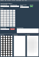
NanoDlp provides a method for creating a mask.  Under "Projector Calibration" there is a button for "Mask Calibration" that takes you to the following form.  The dimensions at the top that I am using are 5, 10, and 200.  Darkness of each cell of the mask can be specified or the entire table loaded via a CSV import (which is a feature added at my request).

When you press the "Update Mask" the actual image used for the mask is updated from the values collected either by manipulating the individual cells or by importing from a CSV paste.  Note that the created file is available on the Raspberry Pi in the printer/public/plates and is named mask.png.  If pulled from the RPi it should, in theory, be useable with CW.

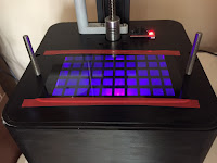
The other thing to note is that when you press the "Preview" button a grid of squares will be projected on the printer as shown below.  BTW, the squares are 200mm in size by virtue of the change I make from the default of 100mm at the top of the form.

More about all of this in Part 2 of this article but it is well worth noting (again) that before you mess about with this particular form you should have taken your vat off of the printer!


Thursday, October 5, 2017

DxP Mask Meter (DxPMM) - The Meter

Following is an overview of the major components that comprise the DxP Mask Meter.
Early Prototype in Case
Test Platform for Componen

The meter is based on an Arduino Nano that can be connected to three sensors, a VEML6070 UV Sensor, a GL5288 Photo Resistor, and an optional thermistor for measuring heat at the GL5288.  The user interface is via an OLED display and two LEDs with a single push button for user input.  Readings can be transcribed manually from the OLED, collected via the Arduino IDE with the meter connected to a PC, or through a bluetooth terminal session (more on the terminal options below).

The meter can be connected to one of two probes, one for the VEML6070 and one for the GL5288 with the optional thermistor.  It will recognize which is attached and read from the appropriate sensor.  Readings are taken every 50 milliseconds and averaged on a rolling basis over a second.  A deviation is calculated that results in a quality metric from zero to greater than ten.  Greater than ten will not be recorded.  The deviation metric is transmitted via bluetooth and can be used to screen for data quality.  The temperature reading is not used at this time.

Initial Screen
Sent Measurement Screen


There are three jumpers on the bottom of the meter that can be used to configure its operation as below:

        000 - UV - Dumb 
       001 - UV - Auto 
       010 - UV - Manual  
       011 - Photo - Dumb
       100 - Photo - Auto
       101 - Photo - Manual
       110 - Not used
       111 - Config via Menu

The configuration menu, activated when all jumpers are on, presents options that are selected by pressing the button on startup (since there is only one button)!  

Wednesday, October 4, 2017

DxP Mask Meter (DxPMM) - Overview

Catchy new name for the UV Meter to help identify it a little more closely to its intended purpose.  It is, after all, not really a pure UV meter.  Part of its functionality does not even read UV but uses the incidental visible light emitted by the UV LED Array as a proxy for the UV light distribution (which seems to work just fine). 

My hope with this project is to have a relatively easy-to-use tool that simplifies the process of creating a mask for the Wanhao D7 as well as other DUP or DLP printers that are driven by NanoDlp.  Note that the meter can be used in two different ways when working with NanoDlp.  In its 'Dumb' meter mode you can use it as the designers of NanoDlp would have expected.  Namely by displaying a mask preview within the Mask Generation Wizard of NanoDlp and then using the meter to adjust cells.

Here is what one version of the process flow might look like:
  1. Connect the meter to a USB power supply using a mini connector.
  2. Use bluetooth on your computer to connect to the meter and start a capture to file session.
  3. Place the measurement grid on top of the LCD of your printer and secure it (you can use other guide methods).
  4. Display the full white calibration screen from NanoDLP.
  5. Position the Photoresistor meter probe to the first cell on the grid (bottom right) and press the button briefly.
  6. When a good reading has been obtained both LEDs will be lit and the screen will tell you to move to the next cell.  Move up one cell.
  7. When you are ready to move to the bottom of the next column to the right press and hold the button for a second.  This will send a line end.
  8. Repeat the above two steps until you have measured all cells.  Do this quickly or in a couple of sessions as readings from the photo resistor will change as it heats up!
  9. Turn off the full white display and close the terminal capture session.
  10. The output captured from the terminal session should be a comma separated stream of numbers of ten rows and ten columns.  Copy these to the clipboard.
  11. Open your copy of my NanoDlp UV Mask Calculator spreadsheet and paste the above values into the sheet named "Paste Here" in the space provided and follow the instructions at the bottom of that page.
  12. On the first sheet of the workbook you can now find the input that NanoDlp needs for a mask to be generated.  Copy it and then paste it into NanoDlp.
There is a lot more that can be done to refine the mask generated above but this is a broad overview of one version of the process.  You will need to do some tuning of the mask with the meter in the "Dumb" mode so you can measure and adjust cells within the NanoDlp Mask Generation Wizard.  Finally, you will want to print some calibration objects!