NanoDlp can compensate for the above "unevenness" by applying a "mask" that adjusts the exposure during the slicing process. The mask is a grayscale image that is darkest where the light source is the brightest and clear where it is the dimmest. During the slicing process NanoDlp marries the mask with the layer being sliced from the model "subtracting" light based on the contents of the mask.
It is important to note that every printer is going to have a slightly different light pattern . With some printers this may not matter and with others it will matter more. You can get improved results running with a generic mask but you really do need one for your printer that matches your light distribution!
 WARNINGS! 1. TAKE YOUR VAT OFF THE PRINTER BEFORE USING THIS FORM! 2. GET SOME UV PROTECTION GLASSES! WARNING!
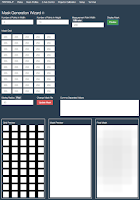
NanoDlp provides a method for creating a mask. Under "Projector Calibration" there is a button for "Mask Calibration" that takes you to the following form. The dimensions at the top that I am using are 5, 10, and 200. Darkness of each cell of the mask can be specified or the entire table loaded via a CSV import (which is a feature added at my request).
 When you press the "Update Mask" the actual image used for the mask is updated from the values collected either by manipulating the individual cells or by importing from a CSV paste. Note that the created file is available on the Raspberry Pi in the printer/public/plates and is named mask.png. If pulled from the RPi it should, in theory, be useable with CW.
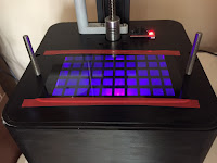
 The other thing to note is that when you press the "Preview" button a grid of squares will be projected on the printer as shown below. BTW, the squares are 200mm in size by virtue of the change I make from the default of 100mm at the top of the form.
More about all of this in Part 2 of this article but it is well worth noting (again) that before you mess about with this particular form you should have taken your vat off of the printer!

Thank you so much looking forward from learning!! If I could request a topic... could you discuss what goes into a resin profile? How you start and how you modify? If I have a 1 cm cube and it comes out at 9.85 what do I change in the profile to make it 1 cm?
ReplyDelete