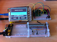
 Here are pictures of the hardware for the prototype of "The App" that I am building. As you can see the BeagleBone Black is sporting an LCD while the Raspberry Pi is not. On the other hand, the Raspberry Pi is decked out with a little joystick which the BeagleBone Black is missing.
-1+(dragged).tiff) The components that are shared by both computers are the:
The components that are shared by both computers are the:- Real Time Clock (RTC)
- Analog Digital Converter (ADC)
- Variable Resistor
The LCD display on the BeagleBone Black is the 3.5 inch cape (LCD3) from Circuitco. It presents the Beaglebone Black's console in 320 by 240 pixels of resolution. 'The App' is presented by Chromium running in full screen kiosk mode and looks very sharp.
Finally, the Raspberry Pi has a joystick attached as a possible option for user input. It is attached to the ADC with two outputs delivering a voltage from -2.5 to +2.5 representing each of the two axis. In addition there is a line to a GPIO pin, attached to a pull down resistor, to register a click.